Notifications
Clear all
General Q&A
1
Posts
1
Users
0
Likes
604
Views

Topic starter
March 30, 2020 8:58 pm
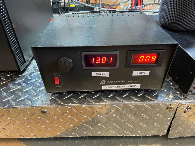
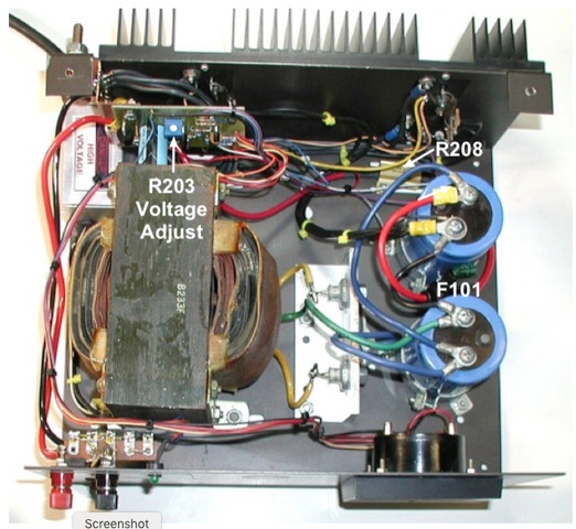
PRA Elmer CommitteeK0EKA Tech Note #1 (Final Version C)Best practices for 12 Volt DC power suppliesWhen you are trying to deliver 35 Amps to a transmitter at 13.8 Volts, your load is (R=E/I) or 13.8/35= 0.394 Ohms. If you are trying to deliver 50 Amps, your load is 13.8/50=0.276 Ohms, so you need to keep any connections from your power supply to the loads at the lowest resistance practical.Here are some best practices I have found to be useful for good power supply performance.K0EKA’s (Ron) refurbished Astron RS-35M power supplyNote the following best practice features in this photo:1. The power supply has been modified to use more accurate and more precise red digital meters for voltage (0-20 Volts) and current (0-50 Amps).2. A voltage adjust added to the front panel and should be set for 13.80 Volts.3. The Power supply has been refurbished per https://www.bwcelectronics.com/articles/WP20A190.pdf web site:
Regulator Characteristics
Extremely rugged
Tolerant of lightning induced current and voltage RFI/EMI tolerant
Very simple
Grounded pass elementsExcellent regulation, low noise + ripple, low output impedance, excellent transient response - not even specified for most Amateur Radio/Consumer products - and very stable under varying load conditions
Fold-back current limiting
Scalable from 3 to 80 Amps
Adjustable 12 to 14 VDC
Low reverse leakage (for charging secondary battery)
LDO (Low Drop Out) - operates with very low input - output differential improving low line performance
Can easily be reworked into most commercial power supplies
Simple 5 kW transient (surge) and reverse voltage protection
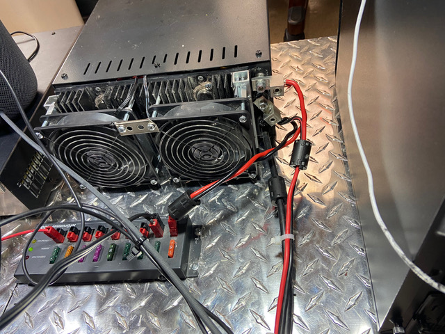
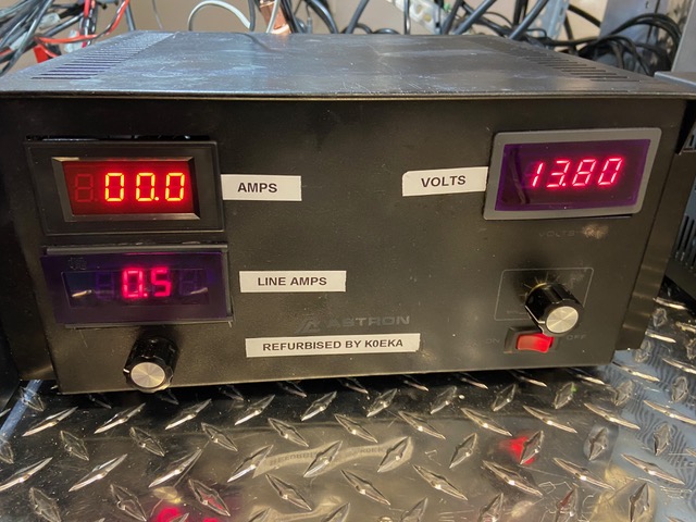
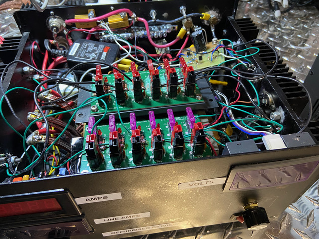
Rear connections to the refurbished Astron RS-35M Power SupplyNote the following best practice features in this photo:1. Power supply is on a metal ground plane.2. Power supply which runs 24/7 has cooling fans added.3. Power supply feeds a fused distribution strip for low current uses.4. Power supply has heavy duty lugs to large AWG wires with tinned ends on output terminals.5. Wire harness runs close to the ground plane and all I/O (wires) has clamp on RF chokes near the power supply chassis.6. Wires are cut short as possible to reduce resistance.7. One of the feeds uses twisted wire. (Ideally the other output wires should also be twisted).8. There is only one connection between the power supply and the end device (avoid multiple connectors in power supply lines).Refurbished Astron 75 AMP linear (no switching) power Supply1. The power supply has been modified to use more accurate and more precise red digital meters for voltage (0-20 Volts) and current (0-50 Amps).2. A voltage adjust added to the front panel and should be set for 13.80 Volts.3. The Power supply has been refurbished per https://www.bwcelectronics.com/articles/WP20A190.pdf web site.Under the Hood of the Refurbished Astron 75 AMP Power SupplyNote:1. 10 AMP fuses were used instead of low ohm resistors to balance the current in the power transistors.2. The heatsinks and chassis was used for the ground return current from the power transistors eliminating 6 #10 AWG wires from the transistors to the negative terminal.3. Power transistors were reduced from 8 to 6 due to the number of fuse circuits available. Power transistors (2N5886) are rated at 25 AMPS max. So 6 should do 150 AMPS with good heat transfer.4. Base circuits were fused for 3 AMPS. Fuses in both circuits also work as a great trouble shooting tool.
3/21/2020Ron Cox K0EKA